High Level Design
Rate Limiting: System Architecture
Why rate limiting matters, the Timer Wheel and Hierarchical Timer Wheel approach, and a full distributed rate-limiting architecture with request sharding.
Why Rate Limiting?#
- Prevent Overload — Controls high request rates to avoid prolonged response times
- Avoid Crashes — Limits requests to prevent Out-of-Memory exceptions
- Stop Cascading Failures — Prevents one service's failure from overloading others
Cascading Failure Example#
| Server | Max Capacity | Current Load | Incoming | Outcome |
|---|---|---|---|---|
| A | 500 | 400 | Rerouted from B | May crash |
| B | 500 | 300 | 600 | Crashes (exceeds capacity) |
Server B crashes → its load shifts to A → A also crashes. This is a cascading failure.
Timer Wheel Approach#
Organizes incoming requests into time slots (buckets) to control the processing rate.
| Aspect | Details |
|---|---|
| Concept | Requests organized into buckets based on arrival time |
| Wheel Size | = timeout value (number of buckets = timeout duration) |
| Bucket Numbering | 0 to Timeout - 1 |
| Request Allocation | bucket = arrival_time % num_buckets |
| Processing | Pulls requests from buckets one by one at a controlled rate |
| Cleanup | Before inserting into a bucket, remove any unprocessed requests from a previous cycle |
Hierarchical Timer Wheel#
Extension of Timer Wheel for managing large ranges of delays efficiently without excessive resources.
How It Works#
- Multiple levels of buckets, each handling a different time granularity:
- Level 1 — short delays (fine-grained buckets)
- Level 2 — longer delays (coarser intervals)
- When a request's timeout is not yet reached at the current level, it cascades to a higher-level bucket
- Avoids having too many buckets at a single level
Full Rate-Limiting Architecture#
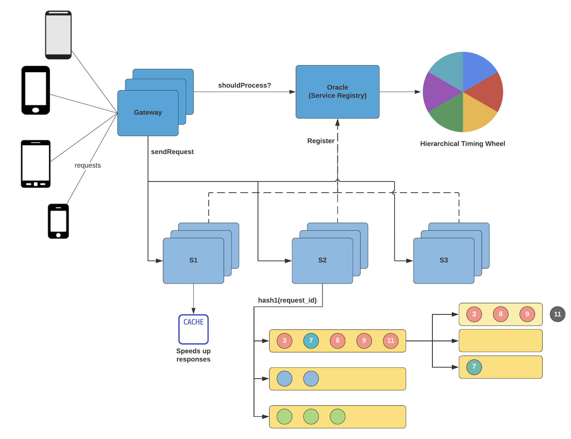
Components#
1. Client Interaction Multiple client devices initiate requests to the system.
2. Gateway Central entry point for all client requests:
- Acts as load balancer
- Sends shouldProcess? query to the Oracle before forwarding
3. Oracle (Service Registry)
- Maintains a registry of available service instances (S1, S2, S3)
- Decides whether a request should be processed
- Uses Hierarchical Timing Wheel for scheduling and time-based throttling
4. Service Servers (S1, S2, S3)
- Gateway sends approved requests to server groups
- Selection based on load + hash1(request_id) (hashing-based routing)
5. Cache Layer
- Each service group has access to a cache
- Speeds up responses for frequently accessed data
6. Request Sharding
- Requests sharded by request_id using a hash function
- Enables load distribution and parallel processing
- Example: request IDs 3, 7, 8, 9, 11 are directed to different queues
Key Concepts#
| Concept | Handled By |
|---|---|
| Load Balancing | Gateway |
| Service Discovery | Oracle |
| Request Scheduling | Hierarchical Timing Wheel |
| Fast Responses | Cache Layer |
| Workload Distribution | Request Sharding / Hashing |